Disconnected tools
Conventional UAV deployments can operate as isolated endpoints. SAADAXA links the aircraft, a dedicated local server and the field operator terminal into one coordinated workflow.
RESPONSE → UNIFIED DSA ARCHITECTUREAERIAL DISASTER ASSISTANCE / 01
SAADAXA is an autonomous aerial disaster assistance and location-tracking system engineered to find survivors, preserve geographic context and relay critical coordinates when satellite navigation and public communications are compromised.
01 THE MISSION PROBLEM
Disaster zones are difficult environments for connected robotics. SAADAXA brings aerial sensing, local processing, geographic recovery and field coordination into one offline-capable system.
Conventional UAV deployments can operate as isolated endpoints. SAADAXA links the aircraft, a dedicated local server and the field operator terminal into one coordinated workflow.
RESPONSE → UNIFIED DSA ARCHITECTURECellular towers, internet backhaul and power infrastructure may be unavailable. The design keeps critical telemetry and survivor coordinates on local and direct radio paths.
RESPONSE → OFFLINE MULTI-TIER LINKSVisual odometry alone provides relative movement. SAADAXA anchors that movement to the last valid geographic fix and projects it back into WGS84 coordinates.
RESPONSE → ENU ANCHOR + RE-ANCHORVideo is not suitable for narrowband LoRa. When Wi-Fi degrades, video and audio are suspended so small, high-priority position and telemetry packets can continue.
RESPONSE → CHANNEL ARBITRATIONThe platform is not designed around uninterrupted connectivity. It is designed around mission continuity when connectivity is interrupted.
SAADAXA · SYSTEM DESIGN INTENT02 SYSTEM ARCHITECTURE
The triangular Drone–Server–App architecture separates airborne autonomy, field-side coordination and operator control—while keeping the complete workflow usable without public internet infrastructure.
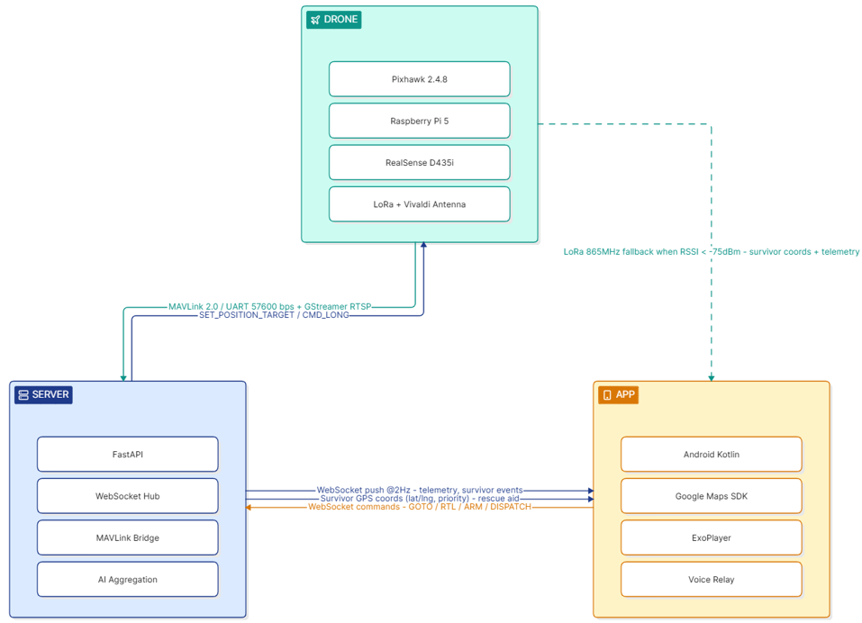
AERIAL EDGE PLATFORM
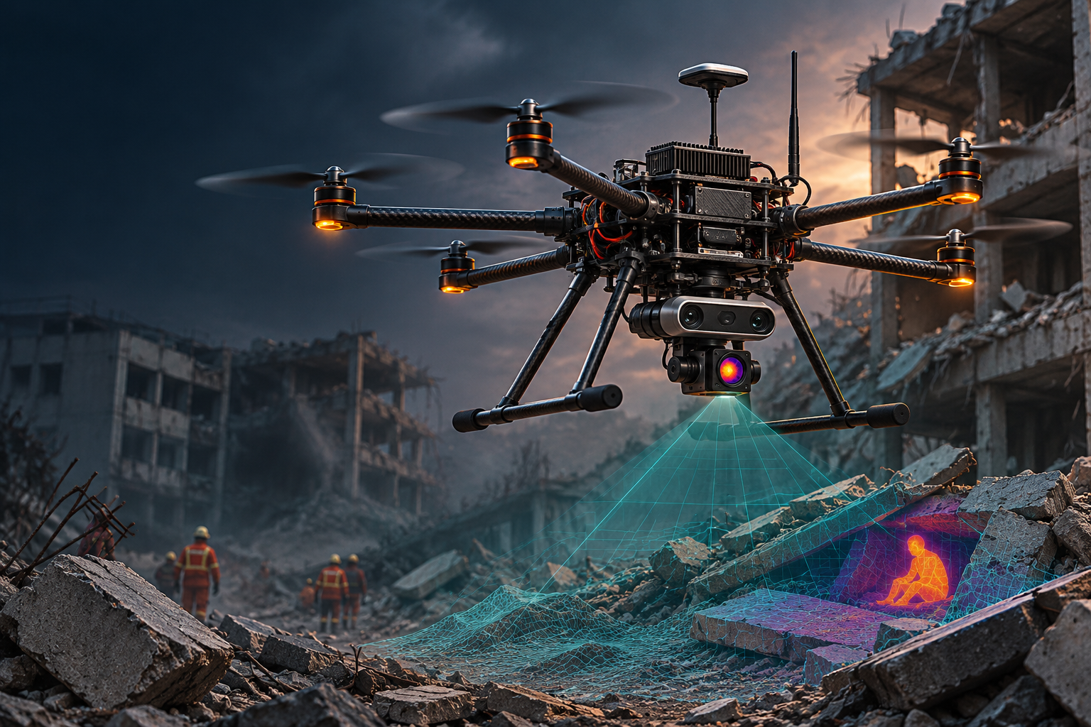
The hexacopter carries the sensor suite, onboard Raspberry Pi 5 compute, Pixhawk flight control, GNSS/visual navigation and dual-channel communications.
03 AIRBORNE PLATFORM
The specification describes a symmetrical carbon-fibre hexacopter, with a central avionics hub and six radial arms. The lower equipment shelf is vibration-isolated to protect optical navigation instruments.
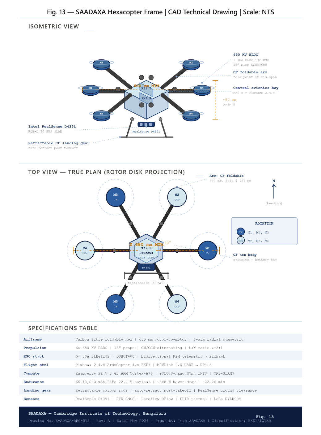 FIGURE 13 / AIRFRAME DESIGN
Six-rotor geometry supports motor-mix compensation in a single-motor anomaly scenario, followed by an automated return-to-launch profile.
04 COMPUTE + SENSOR FUSION
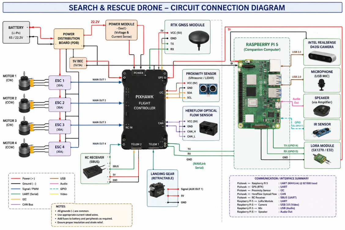
The Raspberry Pi 5 handles high-level autonomy, visual processing and edge intelligence. The Pixhawk handles real-time flight stabilization, state estimation and motor mixing.
Quad-core 64-bit ARM Cortex-A76 · 2.4 GHz · 8 GB RAM
Supervisory compute / edge AI / coordinate recoveryArduCopter 4.x · EKF3 · 32-bit flight controller
Stabilization / navigation estimate / propulsion control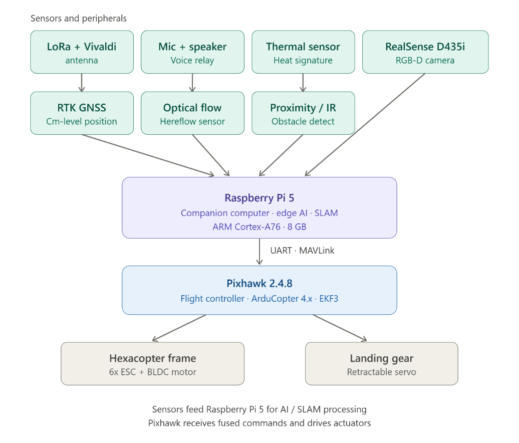
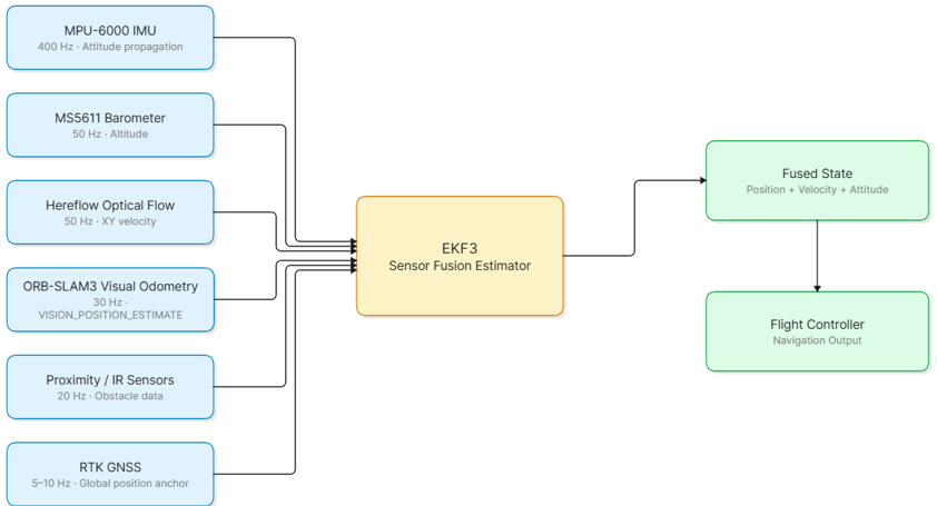
05 GNSS-DENIED NAVIGATION
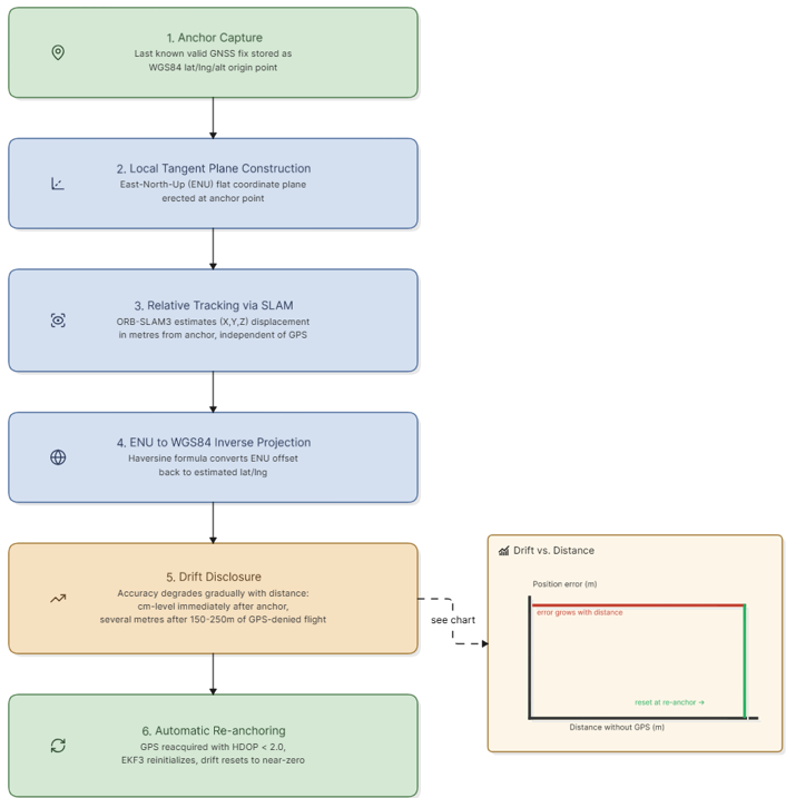
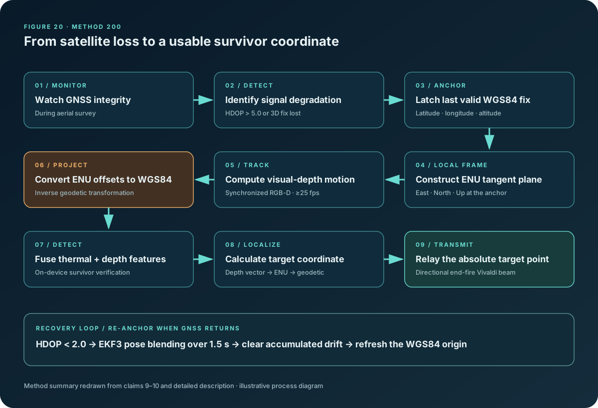
The key navigation concept is anchor-and-re-anchor. The last valid WGS84 position becomes the origin for a local ENU frame; visual-inertial displacement is then projected back into geographic coordinates.
Latch the last validated latitude, longitude and ellipsoidal altitude as a static WGS84 origin.
Construct a local East–North–Up metric tangent plane at the anchor point.
ORB-SLAM3 processes synchronised RealSense RGB-D streams and estimates metric displacement (X, Y, Z).
Inverse geodetic projection converts local East and North offsets into geographic coordinate deltas.
The specification describes near-anchor precision from centimetres to low single-digit metres, with drift potentially accumulating to several metres over 150–250 m.
When GNSS returns with HDOP below 2.0, EKF3 blends the pose over a 1.5-second transition, resets drift and establishes a refreshed origin.
North displacement is converted to angular latitude using the meridional radius at the anchor latitude. East displacement is converted to angular longitude using the prime-vertical radius adjusted by cos(latitude).
Δφ ≈ North / M(φ)Δλ ≈ East / [N(φ) · cos φ]Then add Δφ and Δλ to the anchored latitude and longitude.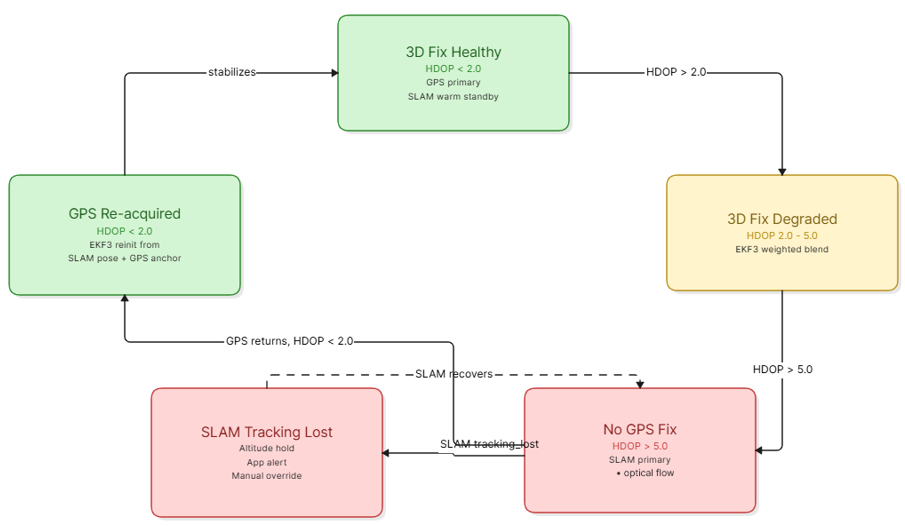
06 ONBOARD EDGE INTELLIGENCE
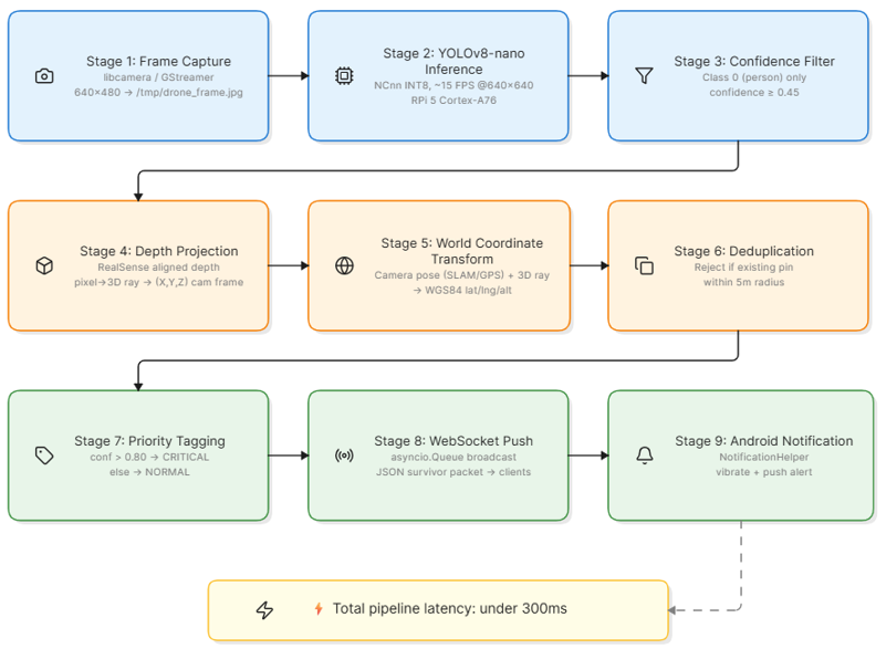
Survivor detection is processed on the aircraft. Visual structure proposes a human candidate, thermal data corroborates the signature, and depth converts the detection into a spatial offset.
Optimised CPU-based inference on the Raspberry Pi 5. The specification describes a compact model designed to avoid cloud dependency and dedicated GPU acceleration.
These are specification-reported simulation figures, not independent test results from this website.
07 RESILIENT COMMUNICATIONS
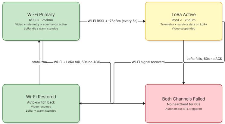
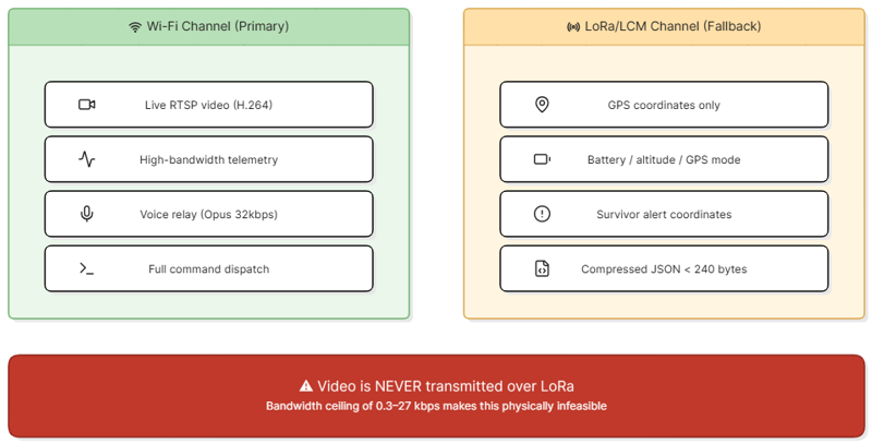
The design deliberately separates high-bandwidth media from low-bandwidth critical coordinates. It does not try to push video through LoRa; it changes the data plan when the link changes.
Wideband operation supports live video, two-way audio and telemetry simultaneously.
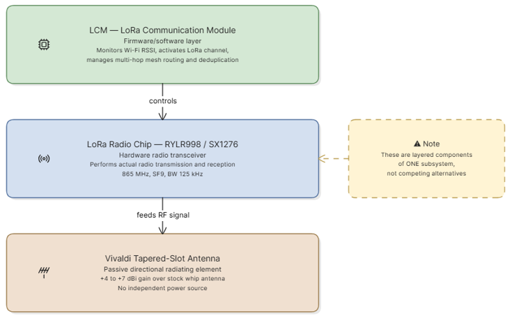
High-throughput path for real-time media and full command interaction when signal quality is healthy.
Low-rate, long-range channel dedicated to the smallest mission-critical payloads—not video or voice.
The end-fire planar tapered-slot Vivaldi antenna focuses radio-frequency energy toward the ground command node. Its passive directive gain is specified at +4 to +7 dBi, without additional electrical power draw.
For comparison, the specification states approximately 1–3 km for a stock whip in damaged or obstructed conditions (8–10 km theoretical unobstructed), versus 2–5 km with the directional Vivaldi in damaged environments.
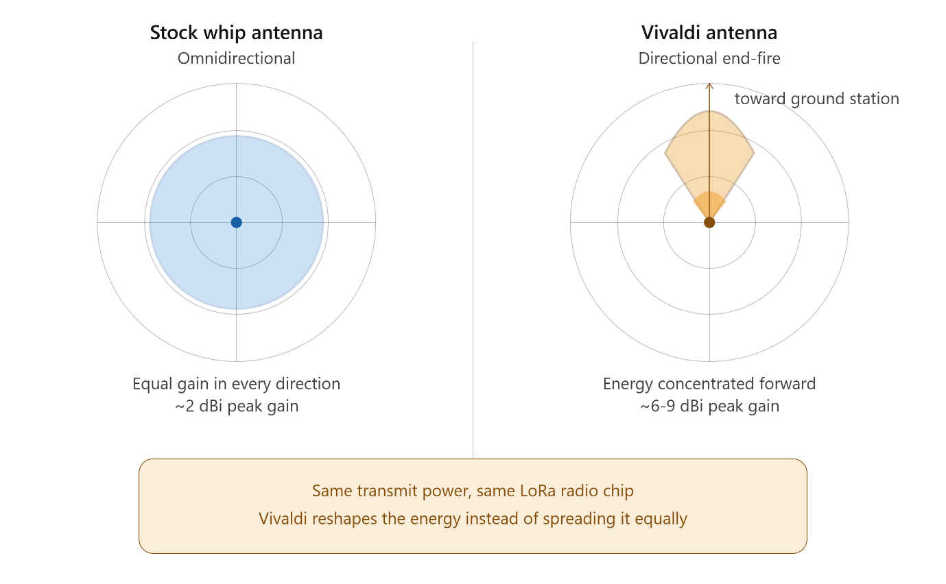 FIG. 09 / RADIATION PATTERN COMPARISON
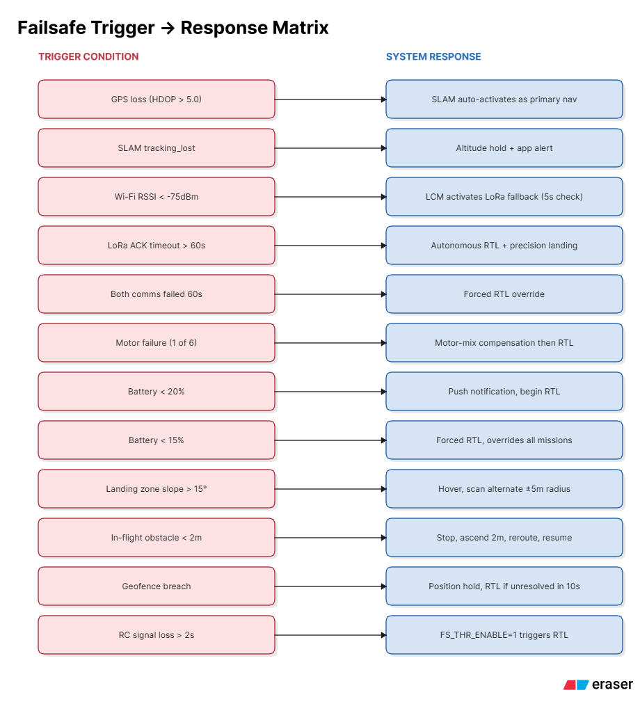
When the Wi-Fi RSSI falls below −75 dBm, video and audio are suspended. The 865 MHz link carries compressed coordinates and core telemetry only. If both channels fail to receive ground-station heartbeat acknowledgements for 60 seconds, the system initiates return-to-launch.
08 MISSION EXECUTION
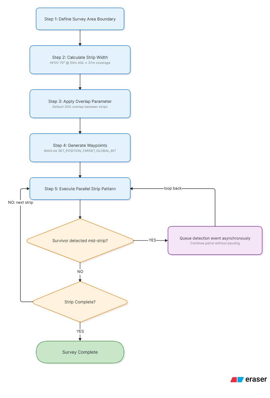
The mission planner decomposes an operator-defined search area into parallel strips. A mid-strip detection interrupts the pattern for confirmation, then the planned survey can resume.
Operator sets the target area and mission limits.
Altitude and camera horizontal field of view determine ground swath width.
Adjacent legs are spaced to maintain a stated 20–30% overlap margin.
A snake-like raster path covers the defined search zone.
The UAV stabilises over the detected target for a confirmation hover, then resumes the survey path.
09 ACTIVE RESCUE INTERACTION
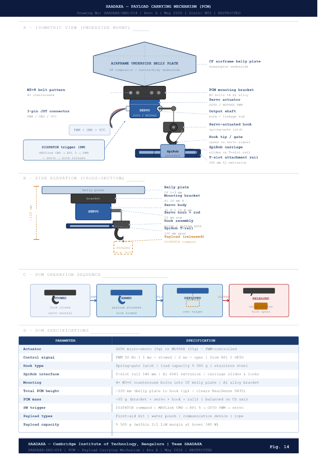
The system extends beyond passive observation. The proposed platform includes two-way acoustic relay and a centrally mounted modular payload release mechanism.
Audio is captured at 16 kHz PCM through ALSA / PyAudio, encoded with Opus at 32 kbps and relayed over WebSocket frames. The reverse path delivers operator audio to the onboard speaker.
 SERVO / QUICK RELEASE
A servo actuator operates a quick-release locking latch under the central hub. The modular mount is described for sensor pods, medical-aid containers or emergency beacon transponders.
10 AUTONOMOUS TOUCHDOWN
Depth point clouds are used to identify a planar landing patch, check slope and obstacles, and verify low lateral drift before the final descent.
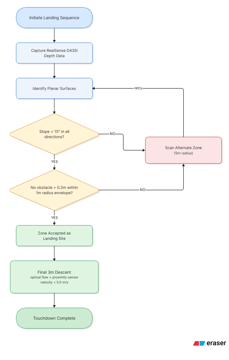 FIG. 12 / AUTONOMOUS LANDING CLEARANCE
11 POWER + ENGINEERING ENVELOPE
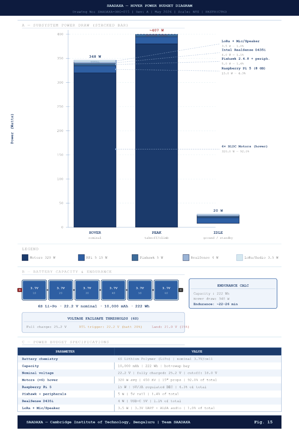
The patent specification describes a 6S, 10 Ah lithium-polymer battery, a nominal 348 W hover-search power estimate and 22–26 minutes of flight endurance.
Estimated total platform power consumption stated for a standard hover-search profile.
Lithium-polymer battery pack with nominal 22.2 V terminal voltage.
Approximate build-cost range mentioned in the supplied patent document.
The document describes hot-swap battery architecture and field charging as mitigations for the stated endurance constraint. Actual flight time will vary with payload, wind, propulsion setup, battery condition and mission profile.
12 FAIL-SAFE DESIGN
Hardware-level ArduCopter failsafes and software supervisors govern degraded navigation, link loss, low battery, motor anomalies and geofence events.
13 SOFTWARE + FIELD INTERFACE
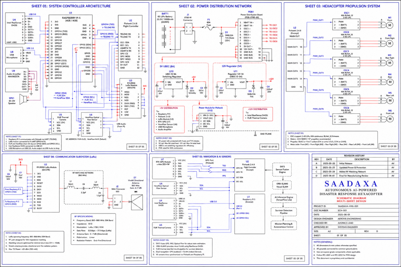
A dedicated local server bridges flight messages, aggregates detections and distributes the current mission picture to the Android field application.
14 CORE METHOD
The independent method claim describes the full chain: monitor satellite integrity, latch an anchor, estimate local displacement, recover absolute coordinates, detect a subject and transmit the target location.
15 OPERATIONAL USE CASES
The specification identifies disaster response, security, remote monitoring, humanitarian operations and infrastructure inspection as potential industrial applications.
Aerial mapping, survivor coordinate relay and field coordination where infrastructure is damaged.
NDMA · NDRF · SDRFAutonomous reconnaissance and direct mesh telemetry without dependence on commercial cellular networks.
DRDO · ARMY · BSFRemote forestry survey and detection of heat signatures in areas with limited communications.
FOREST DEPARTMENTSDepth-aware inspection, survivor localization and tactical communication across rubble fields.
MUNICIPAL FIRE SERVICESUse aerial nodes as multi-hop relay points when terrestrial networks are unavailable.
OFF-GRID FIELD OPERATIONSPotential applications include bridges, dams, pipelines and high-voltage transmission infrastructure.
INSPECTION + ASSESSMENT16 PATENT SCOPE
The supplied specification is titled “Autonomous Aerial Disaster Assistance and Location Tracking System and Its Method for the Same.” The claims cover an integrated UAV system, its supporting functions and the satellite-denied navigation method.
A multi-rotor platform, propulsion and flight control, central computing, satellite-reliant / anchored visual-inertial mode switching, ENU coordinate recovery, visual-depth + thermal survivor detection, and wideband/narrowband communications with directional antenna fallback.
Blend visual-inertial displacement with the re-established satellite fix, reset accumulated spatial drift and establish an updated origin anchor.
An end-fire planar Vivaldi antenna provides a specified +4 to +7 dBi directive gain; compact packets contain target coordinates, altitude, battery status and navigation mode within a 240-byte limit.
Narrowband transceivers receive serialized coordinate payloads from adjacent UAVs and re-radiate them toward a ground terminal.
Verify a landing plane against a 15° inclination limit, 0.3 m obstacle threshold and 1.0 m radius; scan an alternate zone within a 5 m radius and restrict final descent to lateral drift below 0.5 m/s.
Monitor motor behaviour, alter motor-mix commands to surviving motors and execute return-to-launch upon a rotational-frequency anomaly.
Capture and encode local speech, send compressed audio through the wideband link, decode incoming operator audio and disable the audio stream when operating on narrowband radio.
A remote ground node synchronises target coordinates across both links, deduplicates common detections and renders a continuous cartographic representation in the mobile interface during satellite outages.
A method for GNSS-denied navigation and target localization using synchronized visual and depth streams, thermal verification and directional RF transmission of absolute geographic coordinates.
When Wi-Fi RSSI falls below −75 dBm, suspend video and divert coordinates and telemetry to the sub-gigahertz transceiver; after GNSS recovery, blend the fix, clear drift and establish a new anchor.
17 ENGINEERING DRAWING LIBRARY
Browse the supplied patent drawings. Select any figure to enlarge it. Figures 1–18 are original assets extracted from the drawing presentation; Figures 19–20 are clean redraws based on the written specification.
18 TECHNICAL INDEX
A compact index of the principal hardware, software, thresholds and performance values described in the supplied specification.